Tutorial for UCS Based Transformations
The ezdxf version v0.13 introduced a transformation interface for DXF primitives, which makes working with OCS/UCS much easier. This is a new edition of the Tutorial for OCS/UCS Usage. Please read the old tutorial for the basics about the OCS.
For this tutorial we don’t have to worry about the OCS and the extrusion vector,
this is done automatically by the transform() method of each DXF entity.
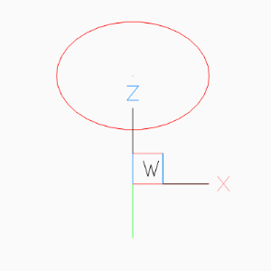
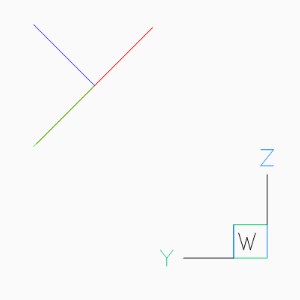
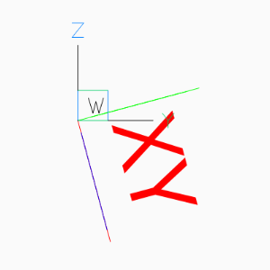
Placing 2D Circle in 3D Space
To recreate the situation of the old tutorial instantiate a new UCS and rotate it around the local x-axis. Use UCS coordinates to place the 2D CIRCLE in 3D space and transform the UCS coordinates to the WCS.
import math
import ezdxf
from ezdxf.math import UCS

doc = ezdxf.new('R2010')
msp = doc.modelspace()

ucs = UCS()  # New default UCS
# All rotation angles in radians, and rotation
# methods always return a new UCS.
ucs = ucs.rotate_local_x(math.radians(-45))
circle = msp.add_circle(
    # Use UCS coordinates to place the 2d circle in 3d space
    center=(0, 0, 2),
    radius=1,
    dxfattribs={'color': 1}
)
circle.transform(ucs.matrix)

# mark center point of circle in WCS
msp.add_point((0, 0, 2), dxfattribs={'color': 1}).transform(ucs.matrix)
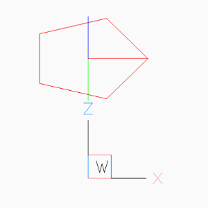
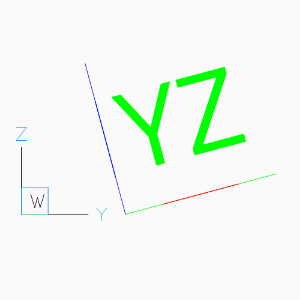
Placing LWPolyline in 3D Space
Simplified LWPOLYLINE example:
# The center of the pentagon should be (0, 2, 2), and the shape is
# rotated around x-axis about -45 degree
ucs = UCS(origin=(0, 2, 2)).rotate_local_x(math.radians(-45))

msp.add_lwpolyline(
    # calculating corner points in UCS coordinates
    points=(Vec3.from_deg_angle((360 / 5) * n) for n in range(5)),
    format='xy',  # ignore z-axis
    close=True,
    dxfattribs={
        'color': 1,
    }
).transform(ucs.matrix)
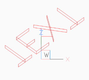
The 2D pentagon in 3D space in BricsCAD Left and Front view.
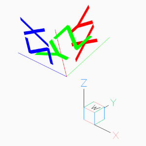
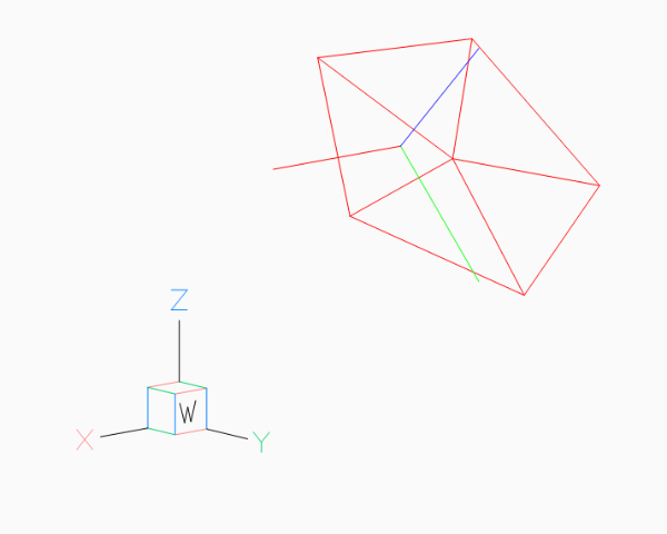
Using UCS to Place 3D Polyline
Simplified POLYLINE example: Using a first UCS to transform the POLYLINE and a second UCS to place the POLYLINE in 3D space.
# using an UCS simplifies 3D operations, but UCS definition can happen later
# calculating corner points in local (UCS) coordinates without Vec3 class
angle = math.radians(360 / 5)
corners_ucs = [(math.cos(angle * n), math.sin(angle * n), 0) for n in range(5)]

# let's do some transformations by UCS
transformation_ucs = UCS().rotate_local_z(math.radians(15))  # 1. rotation around z-axis
transformation_ucs.shift((0, .333, .333))  # 2. translation (inplace)
corners_ucs = list(transformation_ucs.points_to_wcs(corners_ucs))

location_ucs = UCS(origin=(0, 2, 2)).rotate_local_x(math.radians(-45))
msp.add_polyline3d(
    points=corners_ucs,
    close=True,
    dxfattribs={
        'color': 1,
    }
).transform(location_ucs.matrix)

# Add lines from the center of the POLYLINE to the corners
center_ucs = transformation_ucs.to_wcs((0, 0, 0))
for corner in corners_ucs:
    msp.add_line(
        center_ucs, corner, dxfattribs={'color': 1}
    ).transform(location_ucs.matrix)
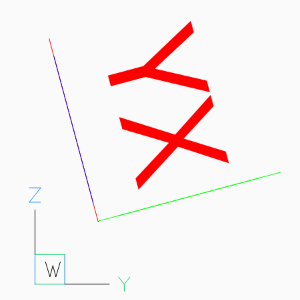
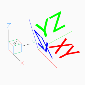
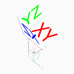
Placing 2D Text in 3D Space
The problem with the text rotation in the old tutorial disappears with the new UCS based transformation method:
AutoCAD supports thickness for the TEXT entity only for .shx fonts and not for true type fonts.
# thickness for text works only with shx fonts not with true type fonts
doc.styles.new('TXT', dxfattribs={'font': 'romans.shx'})

ucs = UCS(origin=(0, 2, 2)).rotate_local_x(math.radians(-45))
text = msp.add_text(
    text="TEXT",
    dxfattribs={
        # text rotation angle in degrees in UCS
        'rotation': -45,
        'thickness': .333,
        'color': 1,
        'style': 'TXT',
    }
)
# set text position in UCS
text.set_pos((0, 0, 0), align='MIDDLE_CENTER')
text.transform(ucs.matrix)
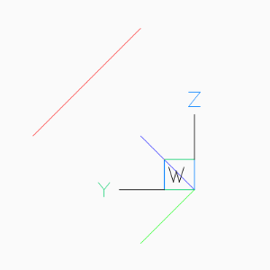
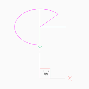
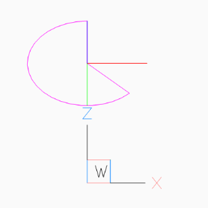
Placing 2D Arc in 3D Space
Same as for the text example, OCS angle transformation can be ignored:
ucs = UCS(origin=(0, 2, 2)).rotate_local_x(math.radians(-45))

CENTER = (0, 0)
START_ANGLE = 45
END_ANGLE = 270

msp.add_arc(
    center=CENTER,
    radius=1,
    start_angle=START_ANGLE,
    end_angle=END_ANGLE,
    dxfattribs={'color': 6},
).transform(ucs.matrix)

msp.add_line(
    start=CENTER,
    end=Vec3.from_deg_angle(START_ANGLE),
    dxfattribs={'color': 6},
).transform(ucs.matrix)

msp.add_line(
    start=CENTER,
    end=Vec3.from_deg_angle(END_ANGLE),
    dxfattribs={'color': 6},
).transform(ucs.matrix)
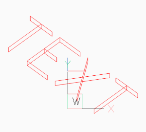
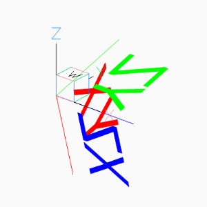
Placing Block References in 3D Space
Despite the fact that block references (INSERT) can contain true 3D entities like LINE or MESH, the INSERT entity uses the same placing principe as TEXT or ARC shown in the previous sections.
To rotate the block reference 15 degrees around the WCS x-axis, we place the block reference in the origin of the UCS, and rotate the UCS 90 degrees around its local y-axis, to align the UCS z-axis with the WCS x-axis:
This is just an excerpt of the important parts, see the whole code of insert.py at github.
doc = ezdxf.new('R2010', setup=True)
blk = doc.blocks.new('CSYS')
setup_csys(blk)
msp = doc.modelspace()

ucs = UCS().rotate_local_y(angle=math.radians(90))
msp.add_blockref(
    'CSYS',
    insert=(0, 0),
    # rotation around the block z-axis (= WCS x-axis)
    dxfattribs={'rotation': 15},
).transform(ucs.matrix)
A more simple approach is to ignore the rotate attribute at all and just
rotate the UCS. To rotate a block reference around any axis rather than the
block z-axis, rotate the UCS into the desired position. The following example
rotates the block reference around the block x-axis by 15 degrees:
ucs = UCS(origin=(1, 2, 0)).rotate_local_x(math.radians(15))
blockref = msp.add_blockref('CSYS', insert=(0, 0, 0))
blockref.transform(ucs.matrix)
The next example shows how to translate a block references with an already established OCS:
# New UCS at the translated location, axis aligned to the WCS
ucs = UCS((-3, -1, 1))
# Transform an already placed block reference, including
# the transformation of the established OCS.
blockref.transform(ucs.matrix)
The next operation is to rotate a block reference with an established OCS, rotation axis is the block y-axis, rotation angle is -90 degrees. The idea is to create an UCS in the origin of the already placed block reference, UCS axis aligned to the block axis and resetting the block reference parameters for a new WCS transformation.
# Get UCS at the block reference insert location, UCS axis aligned
# to the block axis.
ucs = blockref.ucs()
# Rotate UCS around the local y-axis.
ucs = ucs.rotate_local_y(math.radians(-90))
Reset block reference parameters, this places the block reference in the UCS origin and aligns the block axis to the UCS axis, now we do a new transformation from UCS to WCS:
# Reset block reference parameters to place block reference in
# UCS origin, without any rotation and OCS.
blockref.reset_transformation()

# Transform block reference from UCS to WCS
blockref.transform(ucs.matrix)