Tutorial for Ordinate Dimensions
Please read the Tutorial for Linear Dimensions before, if you haven’t.
Note
Ezdxf does not consider all DIMSTYLE variables, so the rendering results are different from CAD applications.
Local Coordinate System
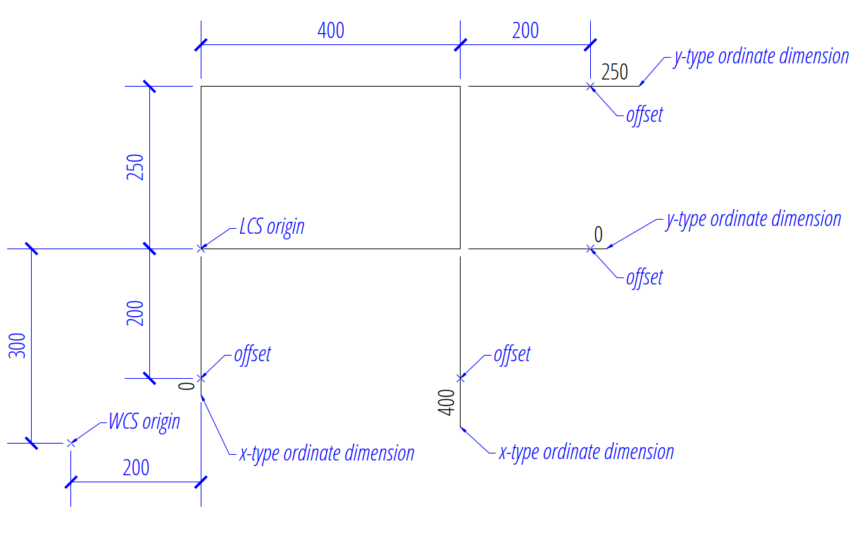
Ordinate dimensioning is used when the x- and the y-coordinates from a location (feature), are the only dimensions necessary. The dimensions to each feature, originate from one datum location, called “origin” in this tutorial.
The local coordinate system (LCS) in which the measurement is done, is defined by the origin and the rotation angle around the z-axis in the rendering UCS, which is the WCS by default.
Factory Methods to Create Ordinate Dimensions
All factory methods for creating ordinate dimensions expect global coordinates to define the feature location.
Global Feature Location
The first example shows ordinate dimensions defined in the render UCS, in this example the WCS, this is how the DIMENSION entity expects the coordinates of the feature location:
import ezdxf
from ezdxf.math import Vec3
from ezdxf.render import forms

# Use argument setup=True to setup the default dimension styles.
doc = ezdxf.new(setup=True)

# Add new entities to the modelspace:
msp = doc.modelspace()
# Add a rectangle: width=4, height = 2.5, lower left corner is WCS(x=2, y=3)
origin = Vec3(2, 3)
msp.add_lwpolyline(
    forms.translate(forms.box(4, 2.5), origin),
    close=True
)

# Add an x-type ordinate DIMENSION with global feature locations:
msp.add_ordinate_x_dim(
    # lower left corner
    feature_location=origin + (0, 0),  # feature location in the WCS
    offset=(0, -2),  # end of leader, relative to the feature location
    origin=origin,
).render()
msp.add_ordinate_x_dim(
    # lower right corner
    feature_location=origin + (4, 0),  # feature location in the WCS
    offset=(0, -2),
    origin=origin,
).render()

# Add an y-type ordinate DIMENSION with global feature locations:
msp.add_ordinate_y_dim(
    # lower right corner
    feature_location=origin + (4, 0),  # feature location in the WCS
    offset=(2, 0),
    origin=origin,
).render()
msp.add_ordinate_y_dim(
    # upper right corner
    feature_location=origin + (4, 2.5),  # feature location in the WCS
    offset=(2, 0),
    origin=origin,
).render()

# Necessary second step to create the BLOCK entity with the dimension geometry.
# Additional processing of the DIMENSION entity could happen between adding
# the entity and the rendering call.
doc.saveas("ord_global_features.dxf")
The return value dim is not a dimension entity, instead a
DimStyleOverride object is
returned, the dimension entity is stored as dim.dimension.
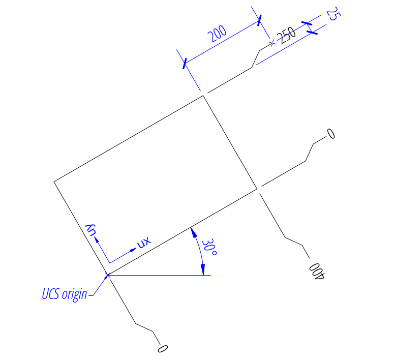
Local Feature Location
The previous examples shows that the calculation of the global feature location is cumbersome and it gets even more complicated for a rotated LCS.
This example shows how to use a render UCS for using
locale coordinates to define the feature locations:
import ezdxf
from ezdxf.math import Vec3, UCS
from ezdxf.render import forms

doc = ezdxf.new(setup=True)
msp = doc.modelspace()

# Create a special DIMSTYLE for "vertical" centered measurement text:
dimstyle = doc.dimstyles.duplicate_entry("EZDXF", "ORD_CENTER")
dimstyle.dxf.dimtad = 0  # "vertical" centered measurement text

# Add a rectangle: width=4, height = 2.5, lower left corner is WCS(x=2, y=3),
# rotated about 30 degrees:
origin = Vec3(2, 3)
msp.add_lwpolyline(
    forms.translate(forms.rotate(forms.box(4, 2.5), 30), origin),
    close=True
)

# Define the rotated local render UCS.
# The origin is the lower-left corner of the rectangle and the axis are
# aligned to the rectangle edges:
# The y-axis "uy" is calculated automatically by the right-hand rule.
ucs = UCS(origin, ux=Vec3.from_deg_angle(30), uz=(0, 0, 1))

# Add a x-type ordinate DIMENSION with local feature locations:
# the origin is now the origin of the UCS, which is (0, 0) the default value of
# "origin" and the feature coordinates are located in the UCS:
msp.add_ordinate_x_dim(
    # lower left corner
    feature_location=(0, 0),  # feature location in the UCS
    offset=(0.25, -2),  # # leader with a "knee"
    dimstyle="ORD_CENTER",
).render(ucs=ucs)  # Important when using a render UCS!
msp.add_ordinate_x_dim(
    # lower right corner
    feature_location=(4, 0),  # feature location in the UCS
    offset=(0.25, -2),  # leader with a "knee"
    dimstyle="ORD_CENTER",
).render(ucs=ucs)  # Important when using a render UCS!

# Add a y-type ordinate DIMENSION with local feature coordinates:
msp.add_ordinate_y_dim(
    # lower right corner
    feature_location=(4, 0),  # feature location in the UCS
    offset=(2, 0.25),  # leader with a "knee"
    dimstyle="ORD_CENTER",
).render(ucs=ucs)  # Important when using a render UCS!
msp.add_ordinate_y_dim(
    # upper right corner
    feature_location=(4, 2.5),  # feature location in the UCS
    offset=(2, 0.25),  # leader with a "knee"
    dimstyle="ORD_CENTER",
).render(ucs=ucs)  # Important when using a render UCS!
doc.saveas("ord_local_features.dxf")
Placing Measurement Text
The ezdxf ordinate DIMENSION renderer places the measurement text always at the default location, because the location of the leader end point is given by the argument offset in the factory methods, which provides a flexible way to place the measurement text, overriding the text location by an explicit user location is not supported, also the user text rotation is not supported, the text is always aligned to the local coordinate system x- and y-axis.
See also
Graphical reference of many DIMVARS and some advanced information: DIMSTYLE Table
Source code file standards.py shows how to create your own DIMSTYLES.
The Script dimension_ordinate.py shows examples for angular dimensions.
Overriding Measurement Text
See Linear Dimension Tutorial: Overriding Text Rotation
Measurement Text Formatting and Styling
See Linear Dimension Tutorial: Measurement Text Formatting and Styling
Tolerances and Limits
See Linear Dimension Tutorial: Tolerances and Limits