Tutorial for MultiLeader
A multileader object typically consists of an arrowhead, a horizontal landing (a.k.a. “dogleg”), a leader line or curve, and either a MTEXT object or a BLOCK.
Factory methods of the BaseLayout class to create new
MultiLeader entities:
Because of the complexity of the MULTILEADER entity, the factory method
add_multileader_mtext() returns a
MultiLeaderMTextBuilder instance to build a new entity
and the factory method add_multileader_block()
returns a MultiLeaderBlockBuilder instance.
Due of the lack of good documentation it’s not possible to support all combinations of MULTILEADER properties with decent quality, so stick to recipes and hints shown in this tutorial to get usable results otherwise, you will enter uncharted territory.
The rendering result of the MULTILEADER entity is highly dependent on the CAD application. The MULTILEADER entity does not have a pre-rendered anonymous block of DXF primitives like all DIMENSION entities, so results may vary from CAD application to CAD application. The general support for this entity is only good in Autodesk products other CAD applications often struggle when rendering MULTILEADERS, even my preferred testing application BricsCAD has rendering issues.
Important
MULTILEADER support has flaws in many CAD applications except Autodesk products!
See also
MTEXT Quick Draw
Full Python script: mtext_quick_leader.py
The quick_leader() method of a MTEXT - MULTILEADER entity constructs the
geometry parameters in reverse manner, starting from a given target point:
DXF document setup:
    doc = ezdxf.new(setup=True)
    # Create a new custom MLEADERSTYLE:
    mleaderstyle = doc.mleader_styles.duplicate_entry("Standard", "EZDXF")
    # The required TEXT style "OpenSans" was created by ezdxf.new() because setup is True:
    mleaderstyle.set_mtext_style("OpenSans")
    msp = doc.modelspace()
Draw a red circle to mark the target point:
    target_point = Vec2(40, 15)
    msp.add_circle(
        target_point, radius=0.5, dxfattribs=GfxAttribs(color=colors.RED)
    )
Create four horizontal placed MULTILEADER entities pointing at the target point, the first segment of the leader line is determined by an angle in this example pointing away from the target point:
    for angle in [45, 135, 225, -45]:
        ml_builder = msp.add_multileader_mtext("EZDXF")
        ml_builder.quick_leader(
            f"angle={angle}°\n2nd text line",
            target=target_point,
            segment1=Vec2.from_deg_angle(angle, 14),
        )
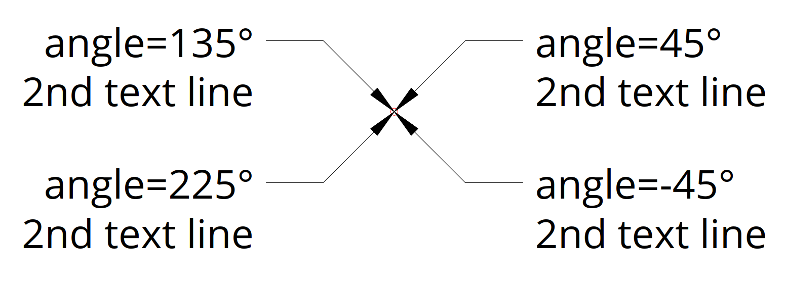
The content is automatically aligned to the end of the leader line. The first segment is a relative vector to the target point and the optional second segment vector is relative to the end of the first segment. The default connection type is horizontal but can be changed to vertical:
A smaller text size is required:
    mleaderstyle = doc.mleader_styles.duplicate_entry("Standard", "EZDXF")
    mleaderstyle.set_mtext_style("OpenSans")
    mleaderstyle.dxf.char_height = 2.0  # set the default char height of MTEXT
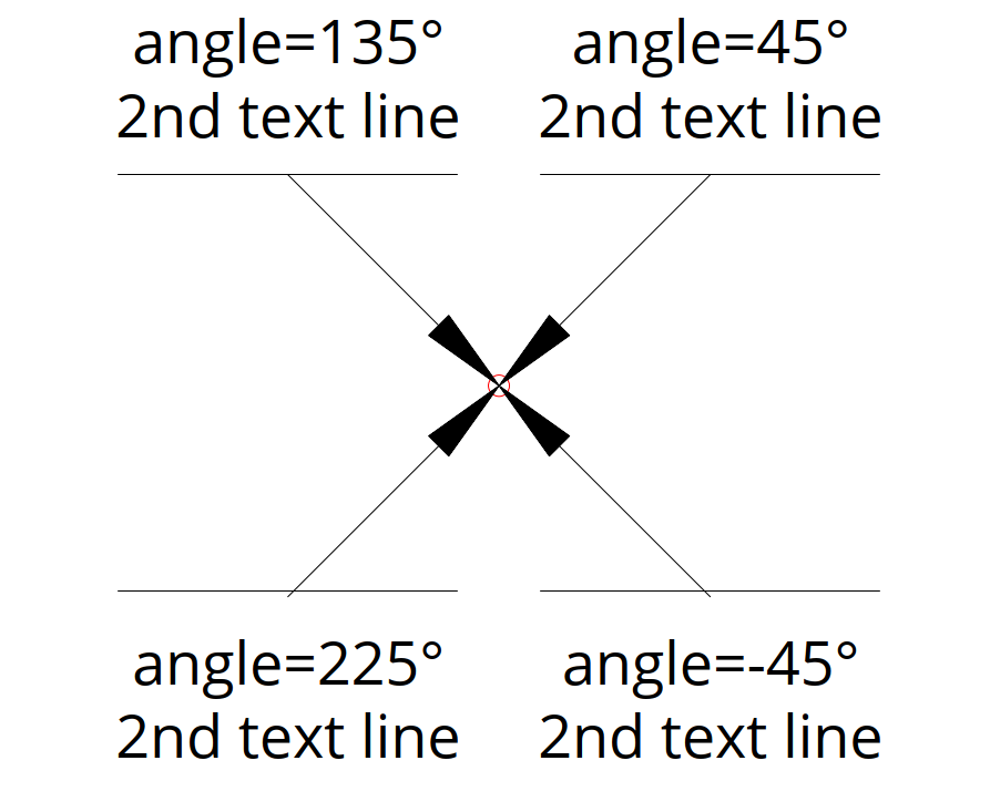
Adding vertical placed MULTILEADER entities:
    for angle in [45, 135, 225, -45]:
        ml_builder = msp.add_multileader_mtext("EZDXF")
        ml_builder.quick_leader(
            f"angle={angle}°\n2nd text line",
            target=target_point,
            segment1=Vec2.from_deg_angle(angle, 14),
            connection_type=mleader.VerticalConnection.center_overline,
        )
This example already shows the limitation caused by different text renderings in various CAD applications. The ezdxf text measurement by matplotlib is different to AutoCAD and BricsCAD and the result is a misalignment of the overline and the leader line.
The DXF file shown in BricsCAD:
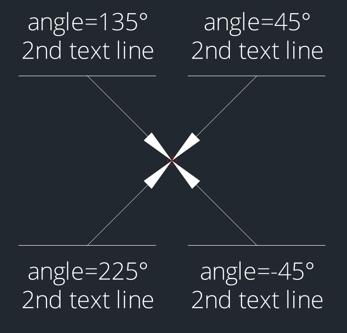
The same DXF file shown with the ezdxf view command (drawing add-on):
My advice is to avoid vertical placed MULTILEADER entities at all and for horizontal placed MULTILEADER entities avoid styles including an “underline” or an “overline”.
The quick_leader() method is not very customizable for ease of use, but
follows the settings of the associated MLeaderStyle.
The following sections show how to have more control when adding MULTILEADER entities.
Create MTEXT Content
Full Python script: mtext_content.py
This section shows how to create a MULTILEADER entity with MTEXT content the manual way with full control over all settings.
For good results the MTEXT alignment should match the leader connection side, e.g. if you attach leaders to the left side also align the MTEXT to the left side, for leaders attached at the right side, align the MTEXT to the right side and if you attach leaders at both sides one side will fit better than the other or maybe a center aligned MTEXT is a good solution, for further details see section MTEXT Alignment.
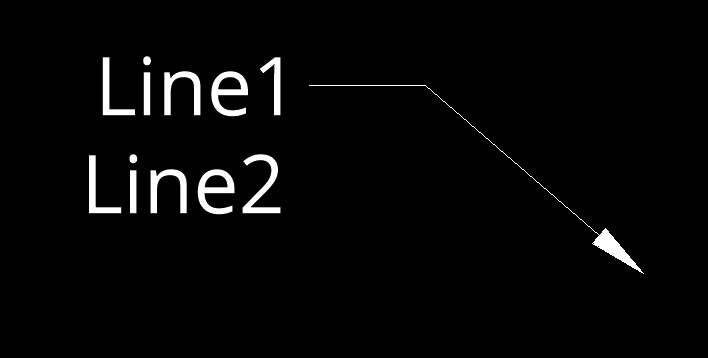
The first example uses the default connection type of the MLEADERSTYLE “Standard” which is “middle of the top line” for left and right attached leaders. The render UCS for this example is the WCS to keep things simple.
Create a new MULTILEADER entity.
ml_builder = msp.add_multileader_mtext("Standard")
Set MTEXT content, text style and alignment.
    ml_builder.set_content(
        "Line1\nLine2",
        style="OpenSans",
        alignment=mleader.TextAlignment.left,  # set MTEXT alignment!
    )
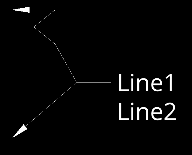
Add the first leader on the left side. The leader points always to the first given vertex and all vertices are given in render UCS coordinates (= WCS in this example).
ml_builder.add_leader_line(mleader.ConnectionSide.left, [Vec2(-20, -15)])
More than one vertex per leader can be used:
    ml_builder.add_leader_line(
        mleader.ConnectionSide.left,
        [Vec2(-20, 15), Vec2(-10, 15), Vec2(-15, 11), Vec2(-10, 7)],
    )
The insert point of the build() method is the alignment point for the
MTEXT content.
ml_builder.build(insert=Vec2(5, 0))
The “dogleg” settings are defined by the MLEADERSTYLE “Standard”.
This example shows a leader attached to the right side and the MTEXT aligned to the right side.
    ml_builder = msp.add_multileader_mtext("Standard")
    ml_builder.set_content(
        "Line1\nLine2",
        style="OpenSans",
        alignment=mleader.TextAlignment.right,  # set MTEXT alignment!
    )
    ml_builder.add_leader_line(mleader.ConnectionSide.right, [Vec2(40, -15)])
    ml_builder.build(insert=Vec2(15, 0))
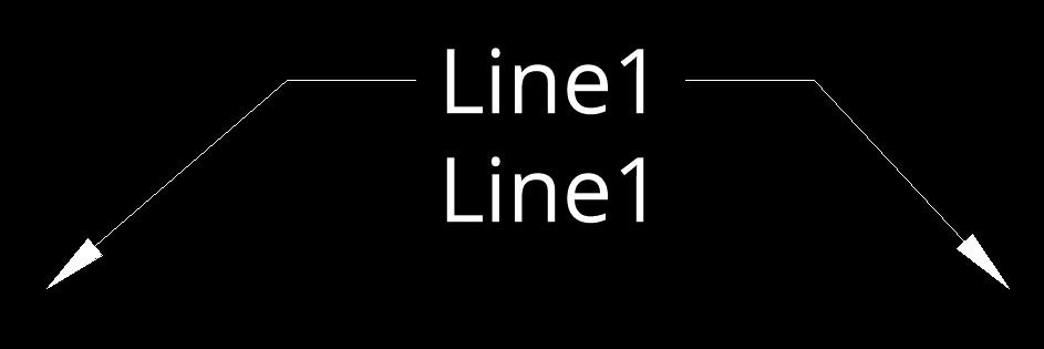
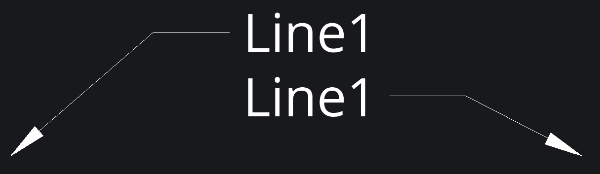
This example shows two leaders attached to both sides and the MTEXT aligned to the left side, which shows that the right landing gap (space between text and start of vertex) is bigger than the gap on the left size. This is due to the different text size calculations from AutoCAD/BricsCAD and Matplotlib. The longer the text, the greater the error.
    ml_builder = msp.add_multileader_mtext("Standard")
    ml_builder.set_content(
        "Line1\nLine1",
        style="OpenSans",
        alignment=mleader.TextAlignment.left,  # set MTEXT alignment!
    )
    ml_builder.add_leader_line(mleader.ConnectionSide.left, [Vec2(-20, -15)])
    ml_builder.add_leader_line(mleader.ConnectionSide.right, [Vec2(40, -15)])
    ml_builder.build(insert=Vec2(5, 0))
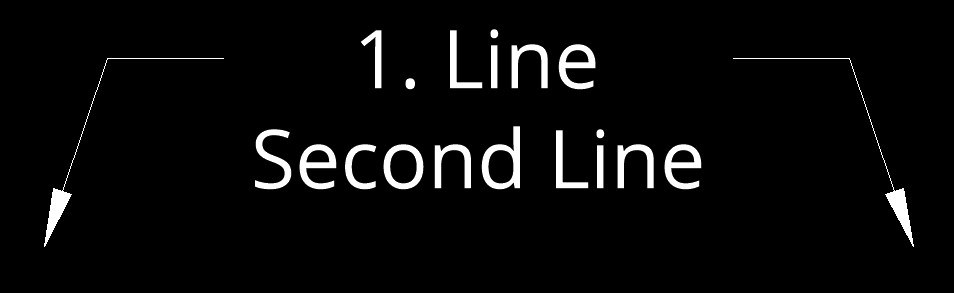
A centered MTEXT alignment gives a more even result.
    ml_builder = msp.add_multileader_mtext("Standard")
    ml_builder.set_content(
        "First Line\n2. Line",
        style="OpenSans",
        alignment=mleader.TextAlignment.center,  # set MTEXT alignment!
    )
    ml_builder.add_leader_line(mleader.ConnectionSide.left, [Vec2(-20, -15)])
    ml_builder.add_leader_line(mleader.ConnectionSide.right, [Vec2(40, -15)])
    ml_builder.build(insert=Vec2(10, 0))
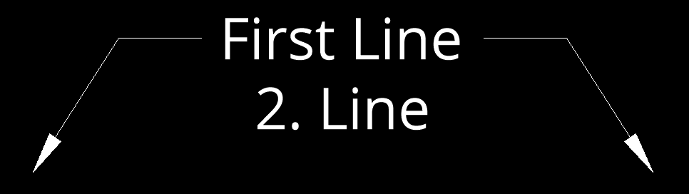
But even this has its disadvantages, the attachment calculation is always based on the bounding box of the MTEXT content.
MTEXT Connection Types
There are four connection sides defined by the enum
ezdxf.render.ConnectionSide:
left
right
top
bottom
The MultiLeader entity supports as the name says multiple leader lines, but all have to have a horizontal (left/right) connection side or a vertical (top/bottom) connection side, it’s not possible to mix left/right and top/bottom connection sides. This is determined by the DXF format.
There are different connection types available for the horizontal and the
vertical connection sides. All leaders connecting to the same side have the
same connection type. The horizontal connection sides support following
connection types, defined by the enum ezdxf.render.HorizontalConnection:
by_style
top_of_top_line
middle_of_top_line
middle_of_text
middle_of_bottom_line
bottom_of_bottom_line
bottom_of_bottom_line_underline (not recommended)
bottom_of_top_line_underline (not recommended)
bottom_of_top_line
bottom_of_top_line_underline_all (not recommended)
The vertical connection sides support following connection types, defined by the
enum ezdxf.render.VerticalConnection:
by_style
center
center_overline (not recommended)
The connection type for each side can be set by the method
set_connection_types(), the default for all
sides is by_style:
    ml_builder.set_connection_types(
        left=mleader.HorizontalConnection.middle_of_top_line,
        right=mleader.HorizontalConnection.middle_of_bottom_line,
    )
Hint
As shown in the quick draw section using connection types including underlines or overlines do not render well in AutoCAD/BricsCAD because of the different text measurement of matplotlib, therefore it’s not recommended to use any of these connection types when creating MULTILEADERS by ezdxf.
MTEXT Alignment
In contrast to the standalone MTEXT entity supports the MTEXT
content entity only three text alignments defined by the enum
ezdxf.render.TextAlignment.
left
center
right
The MTEXT alignment is set as argument alignment of the
set_content() method and the alignment
point is the insert point of the build()
method.
Create BLOCK Content
Full Python script: block_content.py
This section shows how to create a MULTILEADER entity with BLOCK content the manual way with full control over all settings.
The BLOCK content consist of a BLOCK layout and optional ATTDEF entities which defines the location and DXF attributes of dynamically created ATTRIB entities.
Create the BLOCK content, the full create_square_block() function
can be found in the block_content.py script.
    block = create_square_block(
        doc, size=8.0, margin=0.25, base_point=base_point
    )
Create the MULTILEADER and set the content:
    ml_builder = msp.add_multileader_block(style="Standard")
    ml_builder.set_content(
        name=block.name, alignment=mleader.BlockAlignment.insertion_point
    )
Set the BLOCK attribute content as text:
    ml_builder.set_attribute("ONE", "Data1")
    ml_builder.set_attribute("TWO", "Data2")
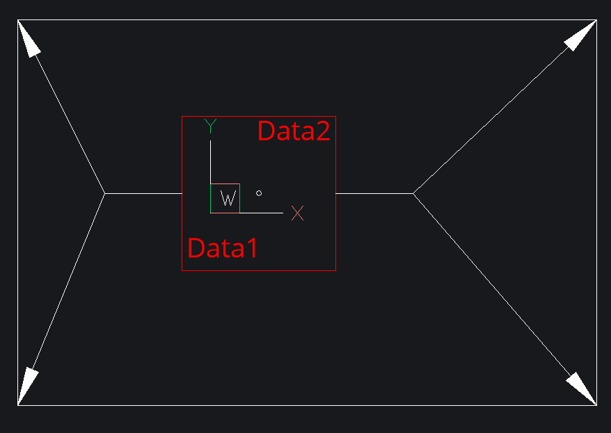
Add some leader lines to the left and right side of the BLOCK:
Construction plane of the entity is defined by a render UCS. The leader lines vertices are expected in render UCS coordinates, which means relative to the UCS origin and this example shows the simple case where the UCS is the WCS which is also the default setting.
    ml_builder.add_leader_line(mleader.ConnectionSide.right, [Vec2(x2, y1)])
    ml_builder.add_leader_line(mleader.ConnectionSide.right, [Vec2(x2, y2)])
    ml_builder.add_leader_line(mleader.ConnectionSide.left, [Vec2(x1, y1)])
    ml_builder.add_leader_line(mleader.ConnectionSide.left, [Vec2(x1, y2)])
Last step is to build the final MULTILEADER entity.
This example uses the alignment type insertion_point where the insert point of
the build() method is the base point of the BLOCK:
ml_builder.build(insert=Vec2(5, 2), rotation=30)
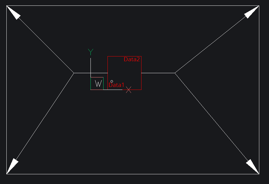
The result is shown in BricsCAD as expected, although BricsCAD shows “Center extents” as attachment type in the properties dialog instead of the correct attachment type “Insertion point”.
BLOCK Connection Types
There are four connection sides defined by the enum
ezdxf.render.ConnectionSide:
left
right
top
bottom
The connection point for leader lines is always the center of the side of the block bounding box the leader is connected to and has the same limitation as for the MTEXT content, it’s not possible to mix the connection sides left/right and top/bottom.
The connection side is set when adding the leader line by the
add_leader_line() method.
Unfortunately BricsCAD has an error in version 22.2.03 and renders all connection types as left/right, this is top/bottom connection shown in Autodesk TrueView 2022:
The top/bottom connection type does not support the “dogleg” feature.
BLOCK Alignment
There are two alignments types, defined by the enum ezdxf.render.BlockAlignment
center_extents
insertion_point
The alignment is set by the set_content() method.
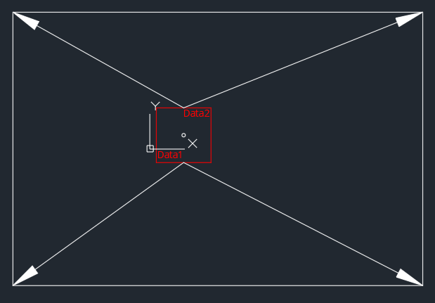
The alignment type center_extent inserts the BLOCK with the center of the
bounding box at the insert point of the build()
method. The insert point is (5, 2) in this example:
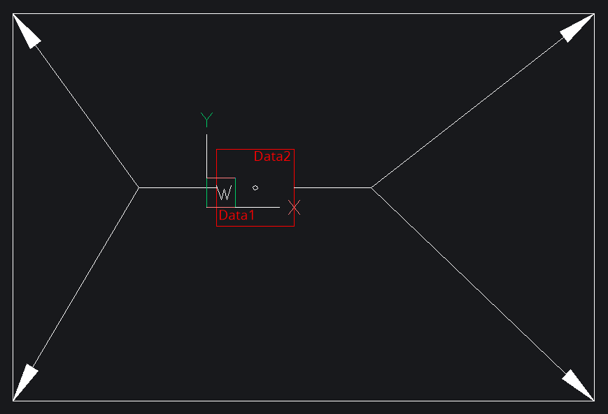
The same MULTILEADER with alignment type insert_point:
BLOCK Scaling
The BLOCK content can be scaled independently from the overall scaling of the MULTILEADER entity:
The block scaling factor is set by the set_content() method:
ml_builder.set_content(
    name=block.name, scale=2.0, alignment=mleader.BlockAlignment.center_extents
)
This is the first example with a block scaling factor of 2. The BLOCK and the attached ATTRIB entities are scaled but not the arrows.
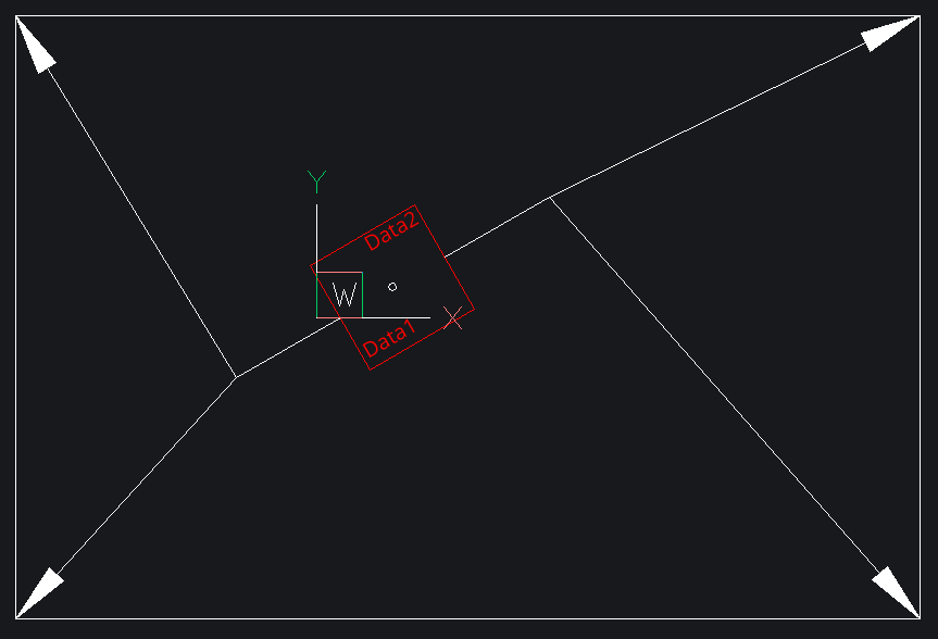
BLOCK Rotation
The rotation around the render UCS z-axis in degrees is applied by the
build() method:
ml_builder.build(insert=Vec2(5, 2), rotation=30)
This is the first example with a rotation of 30 degrees. The BLOCK, the attached ATTRIB entities and the last connection lines (“dogleg”) are rotated.
BLOCK Attributes
BLOCK attributes are defined as ATTDEF entities in the BLOCK layout. This
ATTDEF entities will be replaced by ATTRIB entities at the rendering process
of the CAD application.
Only the text content and the text width factor can be changed for each
MULTILEADER entity individually by the set_attribute()
method. The ATTDEF is addressed by it’s DXF tag attribute:
ml_builder.set_attribute("ONE", "Data1")
ml_builder.set_attribute("TWO", "Data2")
Leader Properties
“Dogleg” Properties
The “dogleg” is the last line segment from the last leader vertex to the MULTILEADER content for polyline leaders.
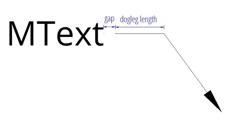
The length of the dogleg and the landing gap size is set by the
set_connection_properties().
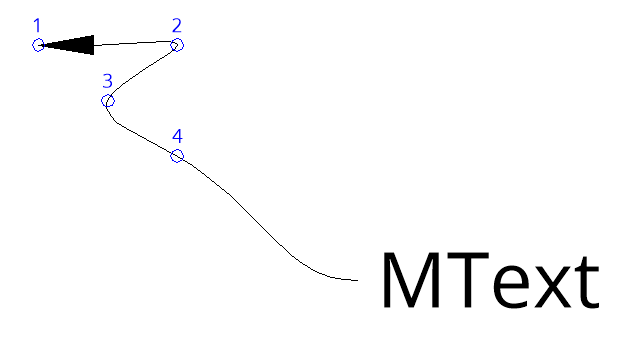
Polyline Leader
A polygon leader line has only straight line segments and is added by the
add_leader_line():
ml_builder.add_leader_line(
    mleader.ConnectionSide.left,
    [Vec2(-20, 15), Vec2(-10, 15), Vec2(-15, 11), Vec2(-10, 7)],
)
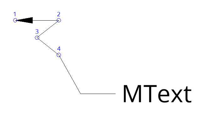
All leader line vertices have render UCS coordinates and the start- and end-vertex of the “dogleg” is calculated automatically.
Spline Leader
A spline leader line has a single curved line as leader line and is also
added by the add_leader_line().
This is spline leader has the same vertices as the previous created polyline
leader:
ml_builder.set_leader_properties(leader_type=mleader.LeaderType.splines)
ml_builder.add_leader_line(
    mleader.ConnectionSide.left,
    [Vec2(-20, 15), Vec2(-10, 15), Vec2(-15, 11), Vec2(-10, 7)],
)
The spline leader has no “dogleg” and spline leaders and polyline leaders can not be mixed in a single MULTILEADER entity.
The leader type is set by the set_leader_properties()
method.
The LeaderType enum:
none
straight_lines
splines
Line Styling
The leader color, linetype and lineweight is set by the
set_leader_properties() method:
ml_builder.set_leader_properties(
    color=colors.MAGENTA,
    linetype="DASHEDX2",
    lineweight=70,
)
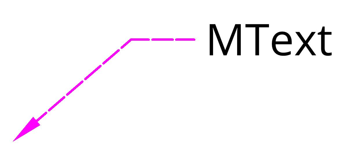
All leader lines have the same properties.
Arrowheads
The arrow head is set by the set_arrow_properties()
method:
from ezdxf.render import ARROWS
ml_builder.set_arrow_properties(name=ARROWS.closed_blank, size=8.0)
All leader lines have the same arrow head and size.
The available arrow heads are defined in the ARROWS
object.
Overall Scaling
The overall scaling has to be applied by the
set_overall_scaling() method
and scales the MTEXT or BLOCK content and the arrows.
Setup MLEADERSTYLE
The MLeaderStyle stores many of the MULTILEADER
settings but most of them are copied to the MULTILINE entity at initialization.
So changing the MLEADERSTYLE style afterwards has little to no effect for
existing MULTILEADER entities.
Create a new MLEADERSTYLE called “MY_STYLE” and set the MTEXT style to “OpenSans”:
my_style = doc.mleader_styles.duplicate_entry("Standard", "MY_STYLE")
my_style.set_mtext_style("OpenSans")
The style for a MULTILEADER is set at the add_multileader_mtext()
and add_multileader_block() factory methods.