Tutorial for Arc Dimensions
Please read the Tutorial for Linear Dimensions before, if you haven’t. This is a repetition of the Tutorial for Angular Dimensions, because ezdxf reuses the angular dimension to render arc dimensions. This approach is very different to CAD applications, but also much less work.
Note
Ezdxf does not render the arc dimension like CAD applications and does not consider all DIMSTYLE variables, so the rendering results are very different from CAD applications.
Dimension Style “EZ_CURVED”
All factory methods to create arc dimensions uses the dimension style “EZ_CURVED” for curved dimension lines which is defined as:
angle unit is decimal degrees,
dimaunit= 0measurement text height = 0.25 (drawing scale = 1:100)
measurement text location is above the dimension line
closed filled arrow and arrow size
dimasz= 0.25dimzin= 2, suppresses trailing zeros (e.g. 12.5000 becomes 12.5)dimarcsym= 2, disables the arc symbol, 0 renders only an open round bracket “(” in front of the text and 1 for arc symbol above the text is not supported, renders like disabled
For more information go to: Dimension Style “EZ_CURVED”
Factory Methods to Create Arc Dimensions
Defined by Center, Radius and Angles
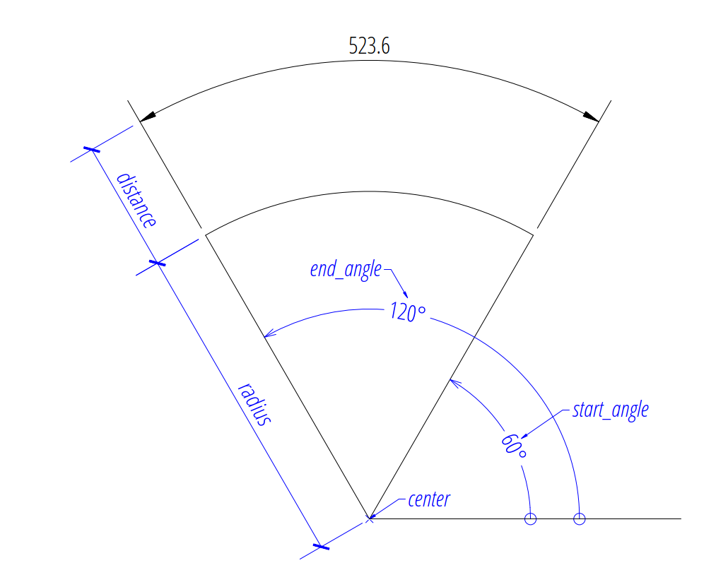
The first example shows an arc dimension defined by the center point, radius, start- and end angles:
import ezdxf

# Use argument setup=True to setup the default dimension styles.
doc = ezdxf.new(setup=True)

# Add new entities to the modelspace:
msp = doc.modelspace()

# Add an arc DIMENSION defined by the center point, start- and end angles,
# the measurement text is placed at the default location above the dimension
# line:
dim = msp.add_arc_dim_cra(
    center=(5, 5),  # center point of the angle
    radius=5,  # distance from center point to the start of the extension lines
    start_angle=60,  # start angle in degrees
    end_angle=120,  # end angle in degrees
    distance=2,  # distance from start of the extension lines to the dimension line
    dimstyle="EZ_CURVED",  # default angular dimension style
)

# Necessary second step to create the BLOCK entity with the dimension geometry.
# Additional processing of the DIMENSION entity could happen between adding
# the entity and the rendering call.
dim.render()
doc.saveas("arc_dimension_cra.dxf")
The return value dim is not a dimension entity, instead a
DimStyleOverride object is
returned, the dimension entity is stored as dim.dimension.
Arc by 3 Points
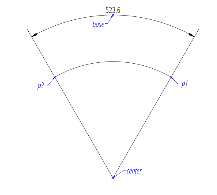
The next example shows an angular dimension defined by three points, a center point and the two end points of the angle legs, the first point defines the radius, the second point defines only the end angle, the distance from the center point is not relevant:
import ezdxf

doc = ezdxf.new(setup=True)
msp = doc.modelspace()

msp.add_arc_dim_3p(
    base=(0, 7),  # location of the dimension line
    center=(0, 0),  # center point
    p1=(2.5, 4.330127018922193),  # 1st point of arc defines start angle and radius
    p2=(-2.5, 4.330127018922194),  # 2nd point defines the end angle
).render()
Angle from ConstructionArc
The ezdxf.math.ConstructionArc provides various class methods for
creating arcs and the construction tool can be created from an ARC entity.
Add an angular dimension to an ARC entity:
import ezdxf

doc = ezdxf.new(setup=True)
msp = doc.modelspace()

arc = msp.add_arc(
    center=(0, 0),
    radius=5,
    start_angle = 60,
    end_angle = 120,
)
msp.add_arc_dim_arc(
    arc.construction_tool(),
    distance=2,
).render()
Placing Measurement Text
The default location of the measurement text depends on various
DimStyle parameters and is applied if no user defined
text location is defined.
Note
Not all possibles features of DIMSTYLE are supported by the ezdxf rendering
procedure and especially for the arc dimension there are less features
implemented than for the linear dimension because of the lack of good
documentation. If the arc symbol is enabled (dimarcsym = 0) only an
open round bracket “(” is rendered in front of the measurement text!
See also
Graphical reference of many DIMVARS and some advanced information: DIMSTYLE Table
Source code file standards.py shows how to create your own DIMSTYLES.
The Script dimension_arc.py shows examples for angular dimensions.
Default Text Locations
The DIMSTYLE “EZ_CURVED” places the measurement text in the center of the angle above the dimension line. The first examples above show the measurement text at the default text location.
The text direction angle is always perpendicular to the line from the text center to the center point of the angle unless this angle is manually overridden.
Arrows and measurement text are placed “outside” automatically if the available space between the extension lines isn’t sufficient.
For more information go to: Default Text Locations
Shift Text From Default Location
The method shift_text() shifts the measurement text away from the default
location. The shifting direction is aligned to the text rotation of the default
measurement text.
For more information go to: Shift Text From Default Location
User Defined Text Locations
Beside the default location it is always possible to override the text location by a user defined location.
The coordinates of user locations are located in the rendering UCS and the default rendering UCS is the WCS.
For more information go to: User Defined Text Locations
Absolute User Location
Absolute placing of the measurement text means relative to the origin of the render UCS.
For more information go to: User Defined Text Locations
Relative User Location
Relative placing of the measurement text means relative to the middle of the dimension line.
For more information go to: User Defined Text Locations
Adding a Leader
Add a leader line to the measurement text and set the text rotation to “horizontal”.
For more information go to: User Defined Text Locations
Overriding Text Rotation
All factory methods supporting the argument text_rotation can override the measurement text rotation. The user defined rotation is relative to the render UCS x-axis (default is WCS).
For more information go to: User Defined Text Locations
Overriding Measurement Text
See Linear Dimension Tutorial: Overriding Text Rotation
Measurement Text Formatting and Styling
See Linear Dimension Tutorial: Measurement Text Formatting and Styling
Tolerances and Limits
See Linear Dimension Tutorial: Tolerances and Limits