Tutorial for Hatch
Create hatches with one boundary path
The simplest form of the Hatch entity has one polyline
path with only straight lines as boundary path:
import ezdxf

# hatch requires DXF R2000 or later
doc = ezdxf.new("R2000")
msp = doc.modelspace()

# by default a solid fill hatch with fill color=7 (white/black)
hatch = msp.add_hatch(color=2)

# every boundary path is a 2D element
# vertex format for the polyline path is: (x, y[, bulge])
# there are no bulge values in this example
hatch.paths.add_polyline_path(
    [(0, 0), (10, 0), (10, 10), (0, 10)], is_closed=True
)

doc.saveas("solid_hatch_polyline_path.dxf")
But like all polyline entities the polyline path can also have bulge values:
import ezdxf

# hatch requires the DXF R2000 or later
doc = ezdxf.new("R2000")
msp = doc.modelspace()

# by default a solid fill hatch with fill color=7 (white/black)
hatch = msp.add_hatch(color=2)

# every boundary path is a 2D element
# vertex format for the polyline path is: (x, y[, bulge])
# bulge value 1 = an arc with diameter=10 (= distance to next vertex * bulge value)
# bulge value > 0 ... arc is right of line
# bulge value < 0 ... arc is left of line
hatch.paths.add_polyline_path(
    [(0, 0, 1), (10, 0), (10, 10, -0.5), (0, 10)], is_closed=True
)

doc.saveas("solid_hatch_polyline_path_with_bulge.dxf")
The most flexible way to define a boundary path is the edge path. An edge path can have multiple edges and each edge can be one of the following elements:
line
EdgePath.add_line()arc
EdgePath.add_arc()ellipse
EdgePath.add_ellipse()spline
EdgePath.add_spline()
Create a solid hatch with an edge path (ellipse) as boundary path:
import ezdxf

# hatch requires the DXF R2000 or later
doc = ezdxf.new("R2000")
msp = doc.modelspace()

# important: major axis >= minor axis (ratio <= 1.)
# minor axis length = major axis length * ratio
msp.add_ellipse((0, 0), major_axis=(0, 10), ratio=0.5)

# by default a solid fill hatch with fill color=7 (white/black)
hatch = msp.add_hatch(color=2)

# every boundary path is a 2D element
edge_path = hatch.paths.add_edge_path()
# each edge path can contain line, arc, ellipse and spline elements
# important: major axis >= minor axis (ratio <= 1.)
edge_path.add_ellipse((0, 0), major_axis=(0, 10), ratio=0.5)

doc.saveas("solid_hatch_ellipse.dxf")
Create hatches with multiple boundary paths (islands)
The DXF attribute hatch_style defines the island detection style:
0 |
nested - altering filled and unfilled areas |
1 |
outer - area between external and outermost path is filled |
2 |
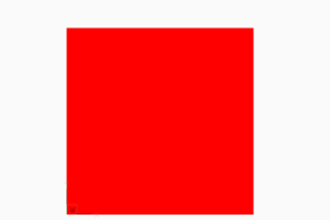
ignore - external path is filled |
hatch = msp.add_hatch(
    color=1,
    dxfattribs={
        "hatch_style": ezdxf.const.HATCH_STYLE_NESTED,
        # 0 = nested: ezdxf.const.HATCH_STYLE_NESTED
        # 1 = outer: ezdxf.const.HATCH_STYLE_OUTERMOST
        # 2 = ignore: ezdxf.const.HATCH_STYLE_IGNORE
    },
)

# The first path has to set flag: 1 = external
# flag const.BOUNDARY_PATH_POLYLINE is added (OR) automatically
hatch.paths.add_polyline_path(
    [(0, 0), (10, 0), (10, 10), (0, 10)],
    is_closed=True,
    flags=ezdxf.const.BOUNDARY_PATH_EXTERNAL,
)
This is also the result for all 4 paths and hatch_style set to 2
(ignore).
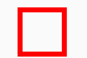
# The second path has to set flag: 16 = outermost
hatch.paths.add_polyline_path(
    [(1, 1), (9, 1), (9, 9), (1, 9)],
    is_closed=True,
    flags=ezdxf.const.BOUNDARY_PATH_OUTERMOST,
)
This is also the result for all 4 paths and hatch_style set to 1
(outer).
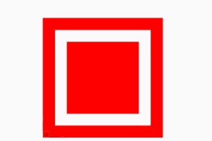
# The third path has to set flag: 0 = default
hatch.paths.add_polyline_path(
    [(2, 2), (8, 2), (8, 8), (2, 8)],
    is_closed=True,
    flags=ezdxf.const.BOUNDARY_PATH_DEFAULT,
)
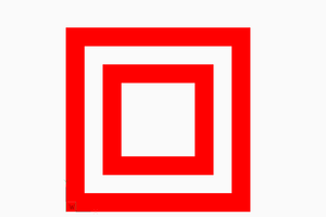
# The forth path has to set flag: 0 = default, and so on
hatch.paths.add_polyline_path(
    [(3, 3), (7, 3), (7, 7), (3, 7)],
    is_closed=True,
    flags=ezdxf.const.BOUNDARY_PATH_DEFAULT,
)

doc.saveas(OUTDIR / "solid_hatch_islands_04.dxf")
The expected result of combinations of various hatch_style values and
paths flags, or the handling of overlapping paths is not documented by the
DXF reference, so don’t ask me, ask Autodesk or just try it by yourself
and post your experience in the forum.
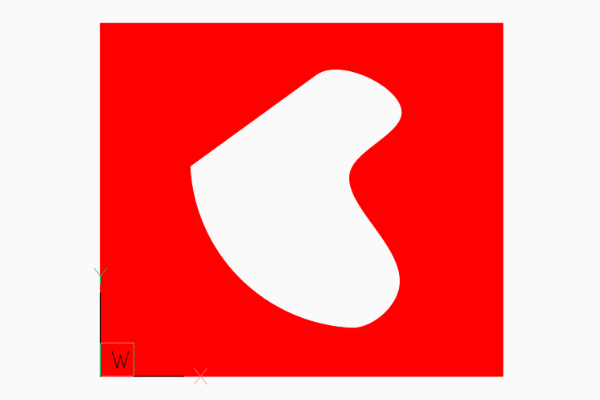
Example for Edge Path Boundary
hatch = msp.add_hatch(color=1)

# 1. polyline path
hatch.paths.add_polyline_path(
    [
        (240, 210, 0),
        (0, 210, 0),
        (0, 0, 0.0),
        (240, 0, 0),
    ],
    is_closed=1,
    flags=ezdxf.const.BOUNDARY_PATH_EXTERNAL,
)
# 2. edge path
edge_path = hatch.paths.add_edge_path(flags=ezdxf.const.BOUNDARY_PATH_OUTERMOST)
edge_path.add_spline(
    control_points=[
        (126.658105895725, 177.0823706957212),
        (141.5497003747484, 187.8907860433995),
        (205.8997365206943, 154.7946313459515),
        (113.0168862297068, 117.8189380884978),
        (202.9816918983783, 63.17222935389572),
        (157.363511042264, 26.4621294342132),
        (144.8204003260554, 28.4383294369643),
    ],
    knot_values=[
        0.0,
        0.0,
        0.0,
        0.0,
        55.20174685732758,
        98.33239645153571,
        175.1126541251052,
        213.2061566683142,
        213.2061566683142,
        213.2061566683142,
        213.2061566683142,
    ],
)
edge_path.add_arc(
    center=(152.6378550678883, 128.3209356351659),
    radius=100.1880612627354,
    start_angle=94.4752130054052,
    end_angle=177.1345242028005,
)
edge_path.add_line(
    (52.57506282464041, 123.3124200796114),
    (126.658105895725, 177.0823706957212),
)
Associative Boundary Paths
A HATCH entity can be associative to a base geometry, which means if the base geometry is edited in a CAD application the HATCH get the same modification. Because ezdxf is not a CAD application, this association is not maintained nor verified by ezdxf, so if you modify the base geometry afterwards the geometry of the boundary path is not updated and no verification is done to check if the associated geometry matches the boundary path, this opens many possibilities to create invalid DXF files: USE WITH CARE.
This example associates a LWPOLYLINE entity to the hatch created from the LWPOLYLINE vertices:
# Create base geometry
lwpolyline = msp.add_lwpolyline(
    [(0, 0, 0), (10, 0, 0.5), (10, 10, 0), (0, 10, 0)],
    format="xyb",
    close=True,
)

hatch = msp.add_hatch(color=1)
path = hatch.paths.add_polyline_path(
    # get path vertices from associated LWPOLYLINE entity
    lwpolyline.get_points(format="xyb"),
    # get closed state also from associated LWPOLYLINE entity
    is_closed=lwpolyline.closed,
)

# Set association between boundary path and LWPOLYLINE
hatch.associate(path, [lwpolyline])
An EdgePath needs associations to all geometry entities forming the
boundary path.
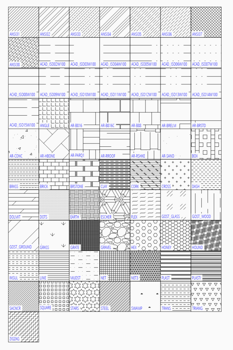
Predefined Hatch Pattern
Use predefined hatch pattern by name:
hatch.set_pattern_fill("ANSI31", scale=0.5)
Load Hatch Patterns From File
CAD applications store the hatch patterns in pattern files with the file extension
.pat. The following script shows how to load and use these pattern files:
EXAMPLE = """; a pattern file

*SOLID, Solid fill
45, 0,0, 0,.125
*ANSI31, ANSI Iron, Brick, Stone masonry
45, 0,0, 0,.125
*ANSI32, ANSI Steel
45, 0,0, 0,.375
45, .176776695,0, 0,.375
*ANSI33, ANSI Bronze, Brass, Copper
45, 0,0, 0,.25
45, .176776695,0, 0,.25, .125,-.0625
*ANSI34, ANSI Plastic, Rubber
45, 0,0, 0,.75
45, .176776695,0, 0,.75
45, .353553391,0, 0,.75
45, .530330086,0, 0,.75
"""

hatch = msp.add_hatch()
# load your pattern file from the file system as string:
# with open("pattern_file.pat", "rt") as fp:
#      EXAMPLE = fp.read()
patterns = pattern.parse(EXAMPLE)

hatch.set_pattern_fill(
    "MyPattern",
    color=7,
    angle=0,  # the overall rotation of the pattern in degrees
    scale=1.0,  # overall scaling of the pattern
    style=0,  # normal hatching style
    pattern_type=0,  # user-defined
    # pattern name without the preceding asterisk
    definition=patterns["ANSI34"],
)
points = [(0, 0), (10, 0), (10, 10), (0, 10)]
hatch.paths.add_polyline_path(points)
msp.add_lwpolyline(points, close=True, dxfattribs={"color": 1})